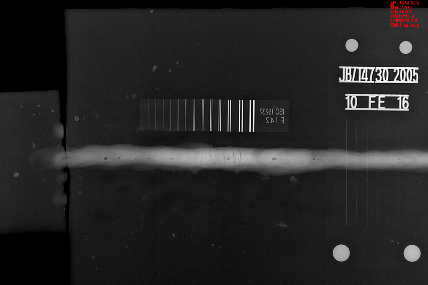
The position information of the defect in each frame of the flaw detection image is composed of two parts. One part is the displacement of the defect on the screen; the other part is the distance traveled by the conveyor carrying the steel pipe, and the distance obtained by the "addition" is the true position information of the defect. The relationship between the two distances is not a simple direct arithmetic addition. This paper will introduce a specific "conversion relationship". After this particular "conversion relationship", the data obtained by adding the two distances is the defect. The correct location information. The displacement of the defect on the screen can be directly obtained by the above-mentioned method of number of defects and size measurement, that is (Xr+X1)/2, and the distance traveled by the transport vehicle is realized by a rotary encoder.
The system uses a rotary encoder, which can generate 1000 pulse signals in one rotation, and the forward distance corresponding to one rotation is 0.5 meters, that is, each pulse of the rotary encoder corresponds to 0.5 mm. In this way, the displacement signal can be converted into a pulse signal by the rotary encoder, and the distance data of the forward movement of the transport vehicle can be transmitted to the flaw detection system program through the single chip microcomputer and the serial communication interface, so that the flaw detection system can use the defect position information for calculation.
-
 Sales@hata-ndt.com
 -
 0086-0371-86172891

