X-ray nondestructive testing system structure and principle
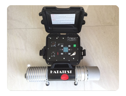
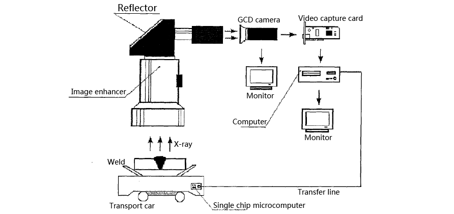
The hardware composition and structure of the ray nondestructive flaw detection automatic detection system are shown in Figure 1. The system is mainly composed of three parts: the signal conversion part, the image processing part and the acquisition and transmission part of the defect position.
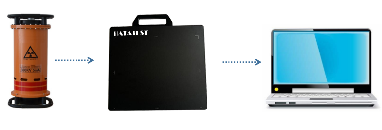
The signal conversion part is mainly composed of an X-ray source, a spiral steel tube, a conveyor car, an image intensifier, a reflector and a CCD camera. The main function of the signal conversion part is to complete the information carrier conversion from x-ray to visible light and the visible to visible image. Photoelectric conversion. The spiral steel pipe is first placed on the conveyor car. While the conveyor car is carrying the spiral steel pipe forward, the rotating roller on the car drives the spiral steel pipe to rotate, so that the spiral weld of the spiral steel pipe is always kept directly below the CCD camera, and the CCD camera The flaw detection image of the spiral weld can always be taken. The X-rays emitted by the X-ray source pass through the spiral steel pipe and the weld zone, and are received by the image intensifier. The image intensifier converts the invisible X-ray inspection information into visible light detection information, and then reflects it into the CCD camera through the mirror. The CCD camera converts the optical signal into an electrical signal (analog data), completes the photoelectric conversion, and sends the flaw detection image to the image processing portion. In the signal conversion section, the CCD camera transmits the captured injured image as an image into the video capture card of the image processing section, and simultaneously displays the original flaw detection image of the frame on the monitor (industrial television) in the image processing section. (analog image). If there are defects such as pores, slag inclusions, or incomplete penetration in the weld area, the defective area transmits more X-rays than the background area (weld area), so it is on the monitor (industrial TV). A bright spot or a bright line is formed in the displayed flaw detection image, and the image processing section uses this feature to detect whether there is a defect in each frame of the flaw detection image.
The image processing part mainly includes a monitor (industrial TV), a video capture card, a computer, a computer display and the like, and the functions of the image processing part mainly include collecting, displaying, processing and storing the collected flaw detection image data. The flaw detection image data (analog data) captured by the CCD camera is first sent to the monitor and displayed on the monitor in real time, and the flaw detection image data is input to the video capture card, and is sampled, quantized, and passed through the video capture card. Encode it after digitizing it. The digitized flaw detection image is also sent to the computer in the form of a frame. In the computer, the fuzzy defect detection algorithm based on the fuzzy recognition criterion is used to detect whether there is a defect in each frame of the flaw detection image (this will be described in detail later). The fuzzy defect detection algorithm) displays the detection results in real time on a computer monitor, and stores the detection results in the memory of the computer for subsequent search and verification.
-
 Sales@hata-ndt.com
 -
 +86 371 63217179